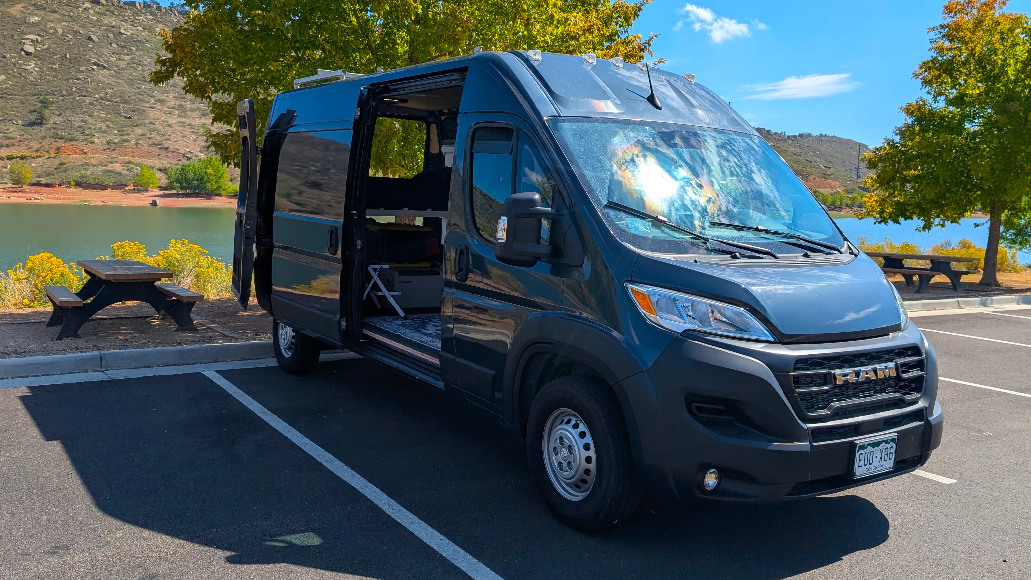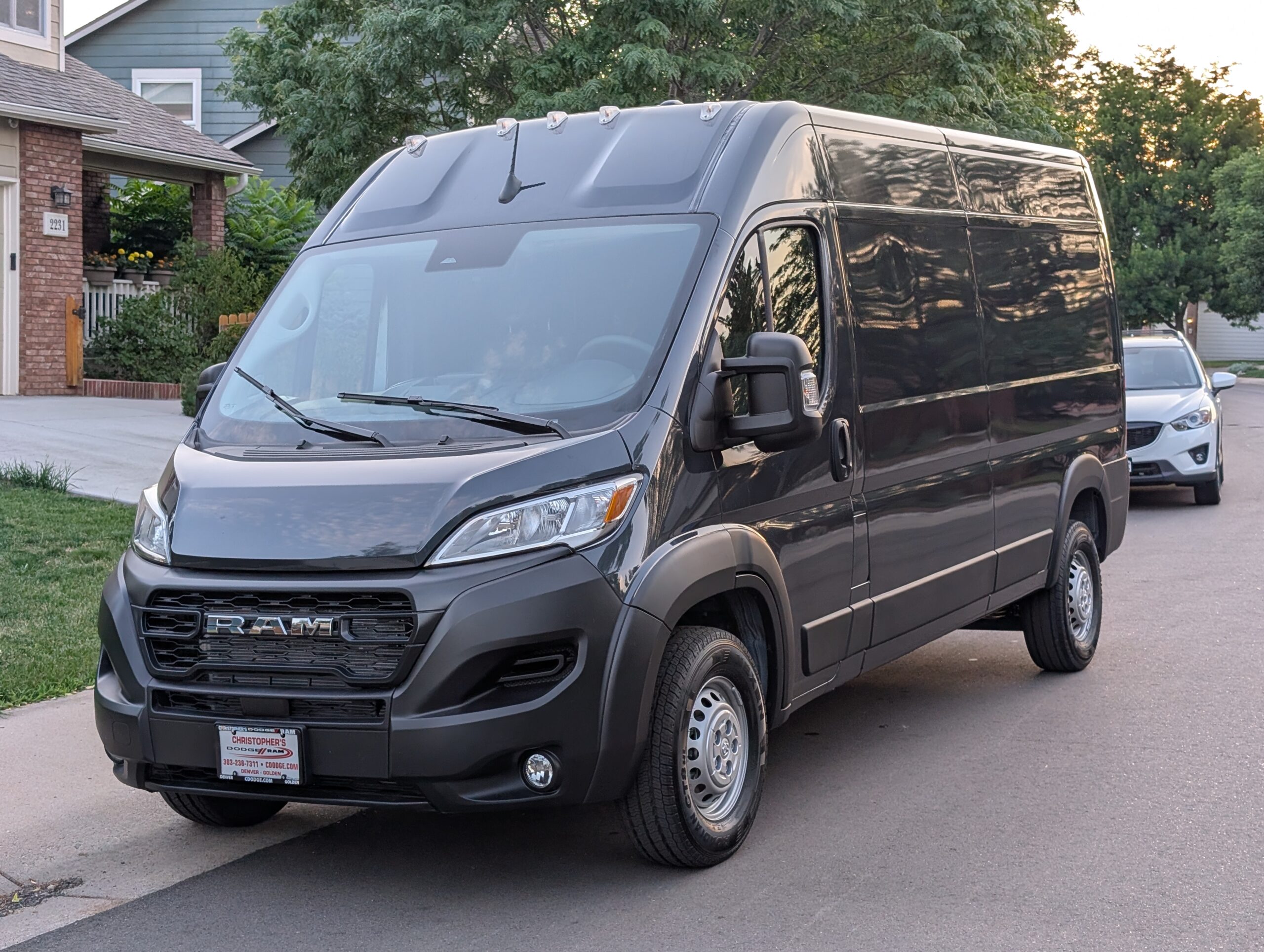
These are primarily personal notes for my own reference as I work through planning, installing, and testing the electrical system in my camper van. I’m documenting decisions, components, and open questions so I can refer back to them as the project progresses. This isn’t intended to be a how-to guide or a finalized electrical design. Some details will undoubtedly change as I install equipment, test things, and learn what works.
What I’m Trying to Accomplish
I’m building a 12-volt electrical system for my 2026 Ram ProMaster 3500 camper van. My goal is to support the electrical equipment I currently use while providing enough flexibility for future additions.
I want to draw electrical power from three sources: 120V AC shore power, the van’s alternator, and eventually solar panels. Power will be stored in a dedicated lithium iron phosphate (LiFePO4) house battery, allowing me to use the electrical system without relying on an external power connection or running the van’s engine.
I also expect to add an inverter to provide 120V AC power from the battery. However, I’m intentionally favoring DC-powered devices wherever practical and limiting the amount of equipment that requires AC power.
I’m approaching this incrementally. Rather than installing everything at once, I’m adding components in stages and testing the system as I go. I’m trying to keep the eventual configuration in mind so that decisions made today don’t result in unnecessary replacement or rework later.
Where Things Stand Now
My electrical system started with a temporary power arrangement using a portable Jackery power station. That was sufficient for getting basic DC equipment operational while I worked through other parts of the van.
More recently, I installed a shore-power connection and started using a Victron Blue Smart IP22 charger (BPC123047102) as a regulated 12.8V DC power supply. Because I don’t have the house battery installed yet, the charger is currently operating in power-supply mode rather than battery-charging mode.
The Victron supplies power directly to a Blue Sea Systems 5026 DC fuse panel, which distributes power to the various DC devices installed throughout the van.
This arrangement works, but it’s temporary. I’m now preparing to reorganize the electrical distribution system around a common set of positive and negative busbars, with a fused distribution block handling the smaller DC circuits.
I’ve selected and ordered most of the equipment needed to add the house battery and alternator charging. Solar and the inverter will come later.
The Planned Electrical Architecture
After considering several possible arrangements, I’ve settled on a relatively simple design using three main distribution components.
The first is a pair of 600A positive and negative busbars, each with six connection points. These will provide the primary electrical connections between the house battery, fused distribution equipment, and eventual inverter.
The second is a RECOIL MPG4 four-circuit Mini-ANL fused distribution block. This provides four individually fused positive circuits and a corresponding negative distribution section. I plan to use it for the shore-power charger, alternator charger, future solar charge controller, and existing DC fuse panel.
The third is my existing Blue Sea Systems 5026, which will continue distributing power to the individual DC appliances and devices.
This arrangement provides some useful separation between the main high-current electrical connections and the smaller charging and distribution circuits.
Electrical System Overview
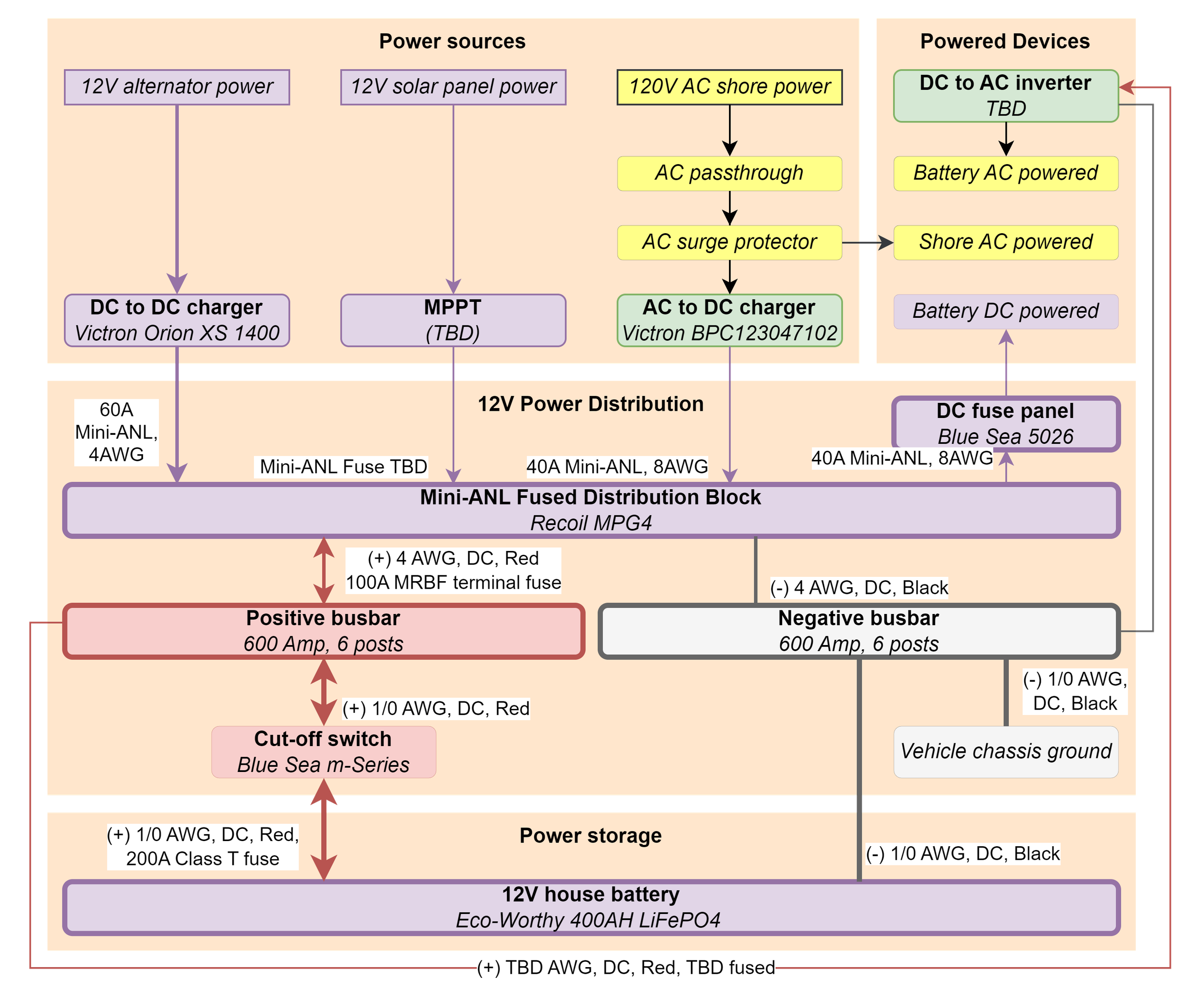
Current planned electrical architecture, November 2026. The diagram includes some components that have not been installed or purchased yet. Wire sizes and fuse ratings reflect current planning and remain subject to verification during installation.
The diagram shows how the components will eventually work together. It doesn’t attempt to capture every electrical connection, protective device, or installation detail.
For example, the alternator charging circuit will require appropriate protection on the vehicle electrical system side in addition to the protection illustrated on the house-battery side.
Shore Power
Shore power was the first part of the electrical system I implemented because it offered a relatively simple way to provide dependable DC power while working on the van at home.
I’m using a Victron Blue Smart IP22 12V/30A charger. Currently, it’s configured to provide a fixed 12.8V DC output, since I don’t yet have a battery installed.
In the updated arrangement, the charger will connect to the RECOIL MPG4 through an 8 AWG positive and negative cable pair. The positive connection will have a 40A Mini-ANL fuse.
Once the house battery is installed, I’ll configure the Victron to use an appropriate LiFePO4 charging profile instead of its current power-supply setting.
I’ll also retain the option to power certain AC devices directly from shore power without involving the house battery or inverter.
Alternator Charging
My van was equipped with an upgraded 220A alternator. I wanted to take advantage of that capacity to charge the house battery while driving.
I’ve selected the Victron Orion XS 1400 DC-to-DC charger, which supports configurable charging current up to 50A in my planned 12V system.
The Orion will connect the vehicle’s electrical system to the house electrical system while regulating the charging power delivered to the battery.
My current plan uses a 4 AWG connection to the RECOIL MPG4, protected by a 60A Mini-ANL fuse on the house side. The vehicle-side wiring and protection will be addressed separately during installation.
One feature I particularly like is the Orion’s configurable charging current and engine shutdown detection. I can start conservatively, verify its behavior with the van’s electrical system, and adjust the settings as appropriate.
Both the shore-power charger and Orion should be able to operate simultaneously when shore power is connected and the engine is running. Their combined maximum output would be approximately 80A, although actual charging current will depend on battery conditions and electrical loads.
House Battery and Main Distribution
I’ve ordered an ECO-WORTHY 12V 400Ah LiFePO4 battery with a metal case, built-in 250A battery management system (BMS), Bluetooth monitoring, and low-temperature protection.
Its nominal energy capacity is approximately 5.12kWh.
I considered both 12V and 24V systems, but ultimately decided to stay with 12V. Most of the electrical equipment I’m installing operates directly from 12V, and I want to avoid unnecessary conversion equipment and complexity.
The battery will connect to the main positive busbar through a Class T fuse and a battery disconnect switch.
For main battery protection, I’ve selected a Go Power FBL-200, which includes a 200A Class T fuse and covered fuse holder. I’ve also ordered a Blue Sea Systems m-Series battery disconnect switch.
The primary battery connections will use 1/0 AWG copper cable. I’m planning a similar 1/0 AWG connection between the negative busbar and an appropriate vehicle chassis grounding point.
I still need to finalize the physical arrangement and verify the installed cable ampacity, connection ratings, and fault protection before connecting the battery.
The battery includes Bluetooth monitoring, so I don’t currently plan to purchase a separate battery-monitoring shunt. I’ll evaluate the built-in monitoring first.
Fused Distribution
The RECOIL MPG4 will provide four smaller fused circuits. My current fuse and wire selections are:
| Circuit | Positive Fuse | Wire Size |
|---|---|---|
| Victron Blue Smart IP22 shore charger | 40A Mini-ANL | 8 AWG |
| Victron Orion XS 1400 | 60A Mini-ANL | 4 AWG |
| Blue Sea Systems 5026 DC panel | 40A Mini-ANL | 8 AWG |
| Future solar MPPT controller | TBD | TBD |
The RECOIL will connect to the main busbars using 4 AWG positive and negative cables.
I’ve selected a Blue Sea Systems 5191 Marine Rated Battery Fuse (MRBF) holder with a 100A fuse to protect the positive feeder between the main positive busbar and RECOIL distribution block.
The MRBF holder mounts directly to a busbar stud, which should eliminate the need for a separate cable between the busbar and fuse holder. I’ll need to confirm the mechanical fit and protective-cover clearance when arranging the components.
The 100A feeder fuse is intended for the system as currently planned. The shore and alternator chargers have a combined maximum output of 80A. When solar is added, I’ll need to revisit the distribution block capacity, feeder current, and fuse selection.
Equipment and Components
The following table captures the major electrical components, wiring, and installation materials I’ve either purchased or am planning to purchase.
Status is current as of November 1, 2026. Items listed as on order have been purchased but haven’t necessarily arrived yet. I’m omitting some details such as additional wire, lugs, fuses, etc. I needed to order, but I added details in the previous illustration where I believe these details are important.
| Component | Description | Status |
|---|---|---|
| Shore-power connection | 120V AC inlet, cord, and surge protection | Available / Installed |
| AC-to-DC charger | Victron Blue Smart IP22 BPC123047102, 12V/30A | Available / In use |
| DC fuse panel | Blue Sea Systems 5026, 12 circuits | Installed |
| Fused distribution block | RECOIL MPG4, four Mini-ANL circuits with negative distribution | Received |
| Main busbars | 600A, six 3/8-inch studs each, red and black with covers | On order |
| House battery | ECO-WORTHY 12V 400Ah LiFePO4, 250A BMS | On order |
| DC-to-DC charger | Victron Orion XS 1400, configurable up to 50A | On order |
| Battery disconnect switch | Blue Sea Systems m-Series, 300A continuous | On order |
| Main battery fuse and holder | Go Power FBL-200, 200A Class T | On order |
| Distribution feeder fuse | Blue Sea Systems 100A MRBF | On order |
| Distribution feeder fuse holder | Blue Sea Systems 5191 | On order |
| Solar panels | Approximately 400W or more, depending on roof space and configuration | Planning |
| Solar MPPT controller | Model and capacity TBD | Planning |
| DC-to-AC inverter | Approximately 2,000W under consideration | Planning |
There will undoubtedly be additional purchases for mounting hardware, electrical enclosures or panels, wire protection, fasteners, terminals, and other installation materials.
I’m not attempting to maintain an exhaustive list of every small component here. The intent is to keep track of the major design decisions and purchases.
What Will This System Power?
I don’t need an especially elaborate electrical system, but I do want enough capacity to make the van practical for longer trips and occasional remote work.
The DC equipment currently installed or anticipated includes interior lighting, the roof ventilation fan, diesel heater, water pump, Starlink Mini, a refrigerator, and USB charging for phones and other portable devices.
The AC side will primarily support a small television, laptop computer, and occasional small appliances. I also have a portable Jackery power station that provides some flexibility while the permanent system is under construction.
I don’t currently plan to install air conditioning. That substantially reduces the electrical demand I need to design around.
Ultimately, I want the system to support normal camping and travel without constantly worrying about available power, but I’m not trying to build an unnecessarily large electrical system.
Solar Power — Later
Solar is still part of the long-term plan, but I’ve decided to focus on the battery, shore charging, and alternator charging first.
I expect to install at least 400W of fixed solar panels, possibly more if the available roof space and electrical requirements make sense.
I haven’t selected the panels, their electrical configuration, or the maximum power point tracking (MPPT) charge controller yet. These decisions will influence the controller output, wire sizing, fuse ratings, and possibly the distribution architecture.
That’s why the solar equipment remains TBD in the diagram.
Inverter — Also Later
I expect to install a pure sine wave inverter, probably somewhere around 2,000W.
However, I haven’t selected a model, and I don’t have an immediate need to install one. Between shore power and the Jackery, I have workable options for the relatively modest amount of AC equipment I’m currently using.
The inverter will connect directly to the main busbars through appropriately sized wiring and overcurrent protection, rather than through the smaller RECOIL distribution block.
When I finalize the inverter, I’ll revisit the main battery cable sizing and fuse requirements. A 2,000W inverter could require more current than the present 200A main battery fuse arrangement is intended to support.
For now, I’m leaving the inverter and its associated wiring details undecided.
Physical Installation and Layout
One of the next major tasks is figuring out how to physically arrange the electrical components.
I haven’t committed to the exact locations of the battery, distribution equipment, fuse holders, and disconnect switch. I want to arrange everything so that the wiring is reasonably short, accessible, and protected, while keeping the installation organized and serviceable.
That may require building a mounting panel, enclosure, or other supporting structure. The exact layout will depend on the space available and the dimensions of the components once I have everything in hand.
I expect to make some changes as I work through that process.
I’m also trying to maintain the same general philosophy I’ve used throughout the van build: avoid unnecessary complexity, keep components accessible, and don’t make permanent decisions until there’s a good reason to do so.
What Comes Next?
My immediate priority is to reorganize the existing shore-powered DC system around the RECOIL distribution block and main busbars.
Once that arrangement is working, I’ll focus on the house battery, including mounting, wiring, the main fuse, and disconnect switch. Then I’ll configure the Victron shore charger for the battery and verify that the system operates properly both with and without shore power.
After that, I’ll install the Orion XS and work through alternator charging.
That sequence should give me a useful battery-powered electrical system before adding either solar or an inverter.
There are still technical details to verify, but I will work through those details at each stage of the installation.
Final Thoughts
The electrical system has evolved quite a bit from my original temporary arrangement, but I think I’ve reached a configuration that makes sense for how I expect to use the van.
I’m trying to strike a balance between simplicity, cost, safety, and future flexibility. I don’t want to spend money on equipment I don’t need, but I also don’t want to save a few dollars now only to find myself replacing major components later.
The most useful part of the approach so far has been treating the electrical system as a series of manageable steps rather than one large installation.
I can continue using the van while working through the build, and each completed step should make it more capable.
I expect this plan to change as I install and test things. That’s part of the reason I’m documenting it now: I’ll have a record of what I was thinking, what I selected, and why.